EJECTOR HEATERS Division
- Ejector vapor heater (vapor-liquid)
- Ejector hydro heater (liquid-liquid)
Ejector heaters are used for fast and efficient heating with 100% utilization of the input heat energy. For drive ejector heaters use the energy of input fluids. Fluid with a higher input pressure is called the driving fluid while the fluid with the lower input pressure is the pumped in fluid.
Operating principle:
When passing through the ejector nozzle the driving fluid transforms most of its thrusting energy into kinetic (speed energy) so it enters the ejector mixing chamber at a great speed (for water vapor at speeds above the speed of sound). In the mixing chamber particles of the driving fluid collide with the particles present belonging to the pumped in fluid, they mix with them transferring part of their kinetic and heat energy (where the driving vapor is completely condensed if the driving fluid is in the vapor phase) forming a joint stream with a stream direction towards the diffuser. Neighboring particles from the pumping pipe replace the particles that have been drawn away thus forming a stream that leads from the pumping pipeline to the mixing chamber of the ejector.
When the stream passes through the diffuser, due to widening of the stream space, the flow slows down, the rate decreases and the pressure increases and reaches the set (desired) value required for further thrusting through the thrusting pipeline.
Advantages:
Compared to classical heaters (heat exchangers, duplicators etc.) they have the following advantages:
- heat utilization is 100% and the construction is simpler;
- their mass and dimensions are small;
- they have no mobile parts so do not require lubrication and maintenance;
- limestone does not form on ejector walls;
- their operation is silent and noiseless;
- they can be mounted fast and easily in all positions;
- they are cheep and have a long lifetime.
This type of heating enables instant attainment of the desired temperature at the ejector output enabling a fast start of the heating installation.
Their special advantage is for processes requiring fast transition from heating to cooling and vice versa as they enable fast exchange of heated and cooled liquid.
3.1 Ejector vapor heaters (vapor-liquid)
Water vapor is used as the driving fluid for these heaters and it delivers all its heat and mechanical energy to the pumped in liquid. They are used for flows from several l/h to several hundred m3/h, for low and high output pressure, production of warm water t<100oC and hot water t>100oC. For certain working conditions pressure of the stream flow at the ejector output can be higher than the driving pressure of vapor p1, as can be seen on diagram 3.1. (Diagram 3.1 is valid for the cold water temperature at the ejector input t2 = 150oC and cold water pressure at the ejector input p2=1.1barabs.
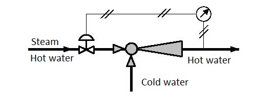
Figure 3.1 Water heating in a line
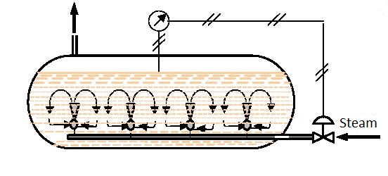
Figure 3.2 Water heating in a reservoir
Application:
They are used for heating water in a pipeline (figure 3.1), for direct introduction of vapor into vessels containing liquid (Figure 3.2 and 3.3), for the preparation of warm water instead of classic heat exchangers (figure 3.4), for sterilization, pasteurization, cooking, bleaching, heating rooms and vessels, in the chemical, pharmaceutical and oil industry, sugar refinement etc.
Example 3.1
Data: The driving pressure of saturated water vapor in front of the ejector is p1=8 barabs, pressure at the ejector output is p3=7.5 barabs, the ejector is immersed into the pumped in water at the depth of 1 m, so the pressure of the pumped in water at the ejector input is p2 = 1.1 barabs, the temperature of the pumped in water at the ejector input is t2 = 150oC
How many kilograms of water can be pumped in with m1 = 1 kg of driving vapor and what will be the temperature of the hot water at the ejector output?
Solution: From diagram 3.1 we can read that for m1=1 kg of driving vapor one can pump in m2 = 12.5 kg of water. The temperature of the heated water at the ejector output is t3 = 5×t = 5×12.2 = 610oC.
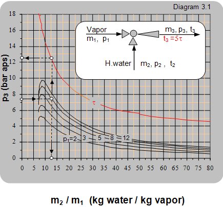
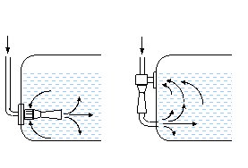 Figure 3.3 Liquid heating using vapor or hot water
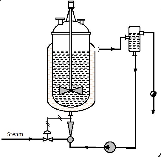
Figure 3.4 Autoclave heating
3.2 Ejector hydro-heaters (liquid-liquid or liquid-vapor)
Liquid is the driving fluid for these heaters and the pumped in fluid can be liquid or vapor. If the liquid is pumped in with liquid then the liquid with the higher pressure is used for drive.
The operating principle is the same as for all ejectors. Due to different flow rates in the ejector mixing chamber both liquids are broken up into the smallest particles. Such broken particles have large active touching surfaces that enable fast, mutual exchange of heat and mechanical energy. The mixed and equally heated hot water leaves the ejector at the pressure required for overcoming the resistance in the thrusting pipeline.
If vapor is used as the pumped in fluid (most often used low pressure remaining vapor or condensate vapor) the driving liquid jet at the ejector input, takes the vapor up, mixes with it and taking it along condenses it at the same time.
Condensation of the pumped in vapor releases heat that heats the driving water. In order to pump in larger amounts of vapor more efficiently the liquid jet can be lead through several serially placed nozzles.
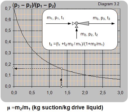
On diagram 3.2 that is valid for ejectors where fluid is the driving and pumped liquid the dependence between the pressure ratio and mass flow ratio between the pumped and driving liquids is given for liquid density r1» r2.
Example 3.2
Data: Driving water has the pressure 6 barabs and temperature t1 = 900oC, pumped in water has the pressure at the ejector input of p2 = 1 barabs (the ejector lies at the pumped water level) and temperature t2 = 200oC. At the ejector output a flow of 10 t/h and temperature of 500oC are required.
What is the flow of driving water m1 and pumped water m2 and what is the pressure of the heated water at the ejector output p3?
Solution:
t3 = (t1·m1+t2·m2)/(m1+m2);
m = m2/m1 = (t1–t3)/(t3–t2) = (90–50)/(50–20) = 1,33.
For the mass flow ratio of m2/m1= 1,33 the pressure ratio is read from the diagram
(p3–p2)/(p1–p2) = 0,16.
From this follows:
p3 = 0,16·(p1-p2) + p2 = 0,16·(6–1)+1 = 1,8 baraps;
m3 = m+m2 = m1·(1+m) = 10;
m1 = m3/(1+m) = 10/(1+1,33) = 4,3 t/h;
m2 = m·m1= 1,33·4,3 = 5,7 t/h.
 |