EJECTOR ABSORBERS Division
Ejectors are widely applied in processes of gas and liquid mixing, in the field of chemical technology and many other technical branches.
All ejector mixing of gas and liquid can be divided into two groups.
The first group: includes ejectors that require pumping in as large amounts of gas per unit liquid flow as possible, where gas solution in the liquid is of no significance.
Such processes are used in ozoning, chlorinating and other devices, for compression of gas using liquids (see Ejector hydro compressors) and ventilation (see Ejector hydro ventilators).
The second group: includes ejectors of which gas solution and complete solution saturation is required. These processes are required in flotation, aeration, for cleaning liquids of oil products and other processes.
Gas solution in liquid is determined by Henry’s law:
m = k·p·Q.
where:
- – m – the mass of dissolved gas,
- k – the solution coefficient that depends on the type of gas and the temperature and liquid type,
- p – the pressure,
- Q – the liquid volume.
The formula shows that the amount of gas that can be dissolved into a liquid depends linearly on coefficient k, pressure p and liquid amount Q, meaning that in a certain liquid volume the amount of dissolved gas can increase by lowering the temperature or increasing the liquid pressure and vice versa.
The solution rate (mass transfer) depends on the mechanism of mass transfer between liquid and gas. In an immobile environment the mechanism of mass transfer is slow and occurs by molecular diffusion. In a mobile environment mass transfer intensifies in a current flow and in a turbulent flow turbulent diffusion occurs due to the influence of pulsation.
Air solution in water is usually not higher than several volume percents, so the pumping in volume coefficient is in the limits of:
q =Q2/Q1 = 0,1 – 0,15
where:
- Q2 – volume flow of the pumped gas,
- Q1 – volume flow of the driving liquid.
Operating principle of the ejector device:
Liquid under pressure p, passing through the ejector jet transforms the thrusting energy into kinetic (rate) energy. Liquid entering the ejector mixing chamber at a great speed catches and takes with it gas present in the chamber, thus forming a completely homogenous fine mixture. Due to different flow rates between the liquid and pumped gas, both fluids are broken up into the smallest particles. Such broken up and fine particle fluids have a large active interacting surface that enables a very fast mutual energy exchange (mechanical, chemical and heat and very fast absorption of pumped gas).
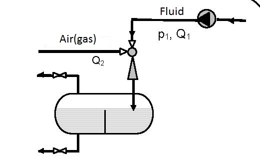
Figure 12.1 One pass liquid with open circulation
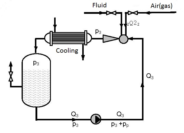
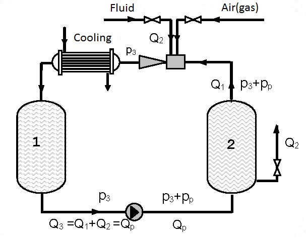
Figure 12.2 Closed circular circulation with cooling abilities
On the path of the current flow through the ejector gases dissolve very fast and solution saturation occurs in the tumultuous turbulent current. The fluid mixture (liquid with dissolved gas and un-dissolved gas) goes to the reservoir where separation of the un-dissolved gas takes place.
The simplest device for gas solution is presented in figure 12.1. Gas solution in liquids is achieved in one pass.
Figures 12.2 and 12.3 present devices with closed circulation, where higher pressures p3 for gas solution are achieved with the same pump (see diagrams 12.1 and 12.2).
On figure 12.2 gas solution is performed under pressure p3 that is higher than the pressure p3 on figure 11.1 as the driving liquid enters the ejector under pressure p3+pp, so the pressure at the ejector output p3 for the same working conditions is higher (see diagrams 12.1 and 12.2). Gas solution can be increased by cooling the gas-liquid mixture at the ejector output.
Q2/Q3 (m3air / m3flow pump for Figure 12.1 and 12.2
Q2/Q3 (m3air / m3flow pump for Figure 12.3)
As the amount of gas pumped in by the ejector and dissolved is small (q0 = Q2/Q1 = 0.1-0.15) in the first approximation the assumption can be made that a single phase fluid i.e. liquid is circulating. Figure 12.3 shows a device in which gas is dissolved in a thrusting ejector pipeline and reservoir 1 under pressure p3 and after passing through the pump solution is performed in the thrusting pump pipeline and reservoir 2 under pressure p3+pp.
Devices constructed according to figures 12.2 and 12.3 enable significant improvement of the utilization degree compared to single pass pumps and ejectors (figure 12.1). Increase of the utilization degree proportionally increases the amount of dissolved gas. The amount of dissolved gas, according to figures 12.2 and 12.3, can be several times higher than the amount of dissolved gas according to figure 12.1. The process can be discontinuous and continual. In a continual process liquid and gas are introduced at the same time as is shown in figures 12.2 and 12.3.
Diagram 12.1 shows the dependence between the pressure ratio p3/pp on the ratio between the volume flow of the pumped air and pump flow Q2/Qp. The diagrams are valid for pumping atmospheric air and pressures p3 and pp are given in bars.
Diagram 12.2 shows an estimated curve of the dependence of the pressure ratio on the flow ratio. As the amount of air pumped in is small it is disregarded so Q2 only represents the liquid flow.
The maximal ratio of manometer pressures p3/pp (bar/bar) that can be attained for Q2 = 0 is:
- for connecting according to scheme 12.1 p3/pp = 0.7
- for connecting according to scheme 12.2 p3/pp = 2.5
- for connecting according to scheme 12.3 p3/pp = 3.5
In the range practically most interesting and most often used the pumping coefficient q = 0.1-0.15 is enough to provide air (gas) for complete liquid saturation.
Example 12.1
According to schemes 12.1 and 12.2 how much atmospheric air (pair = 1 barabs) can be pumped with pump pp = 5 bar and flow Qp = 10 m3/h and put into a reservoir where the pressure is p3 = 3 bar?
Solution: For the pressure ratio p3/pp = 2/5=0.4 diagram 12.1 reads:
- for the installation according to figure 12.1
Q2/Qp =0.3 and Q2 = 0.3×Qp = 0.3×10 = 3 m3air/m3water, - for the installation according to figure 12.2
Q2/Qp =0.6 and Q2 = 0.6×Qp = 0.6×10 = 6 m3air/m3water.
| Figure 12.3 Closed circular circulation with possible cooling |