News Ejektoinzenjering
2/11/2015
Depending on the type of driving fluid aerators are divided into:
- ejector hydro aerators
- ejector gas aerators
In many technical fields (chemical, processing and food industry, mining and waterpower engineering) dirty and polluted water, containing undiluted solids of different origin and size, is removed from the production process. Waste water is most often a solution of gaseous liquid and solid waste materials and can be in the form of emulsions and suspensions.
Purification and treatment of waste water, among other procedures, uses the aeration procedure with an ejector aerator. Aeration in ejector aerators can be performed under different pressures and temperatures, with small and large flows (several hundred m3/h).
Besides waste water ejector aerators can treat: well, depth, spring and other waters containing dissolved minerals. Waters containing dissolved minerals are not tasty and are unsuitable for consumption. For this reason underground water, besides rare exceptions, must be, before use, treated and purified from dissolved compounds or iron and manganese. Increase of the amount of dissolved oxygen in water decreases the amount of dissolved iron and manganese.
De-ferrization and de-manganization can be performed in objects on the surface of the earth and deep below. In objects on the surface oxidation can be performed in continual and clip circular processes. Continual aeration (figures 14.1)
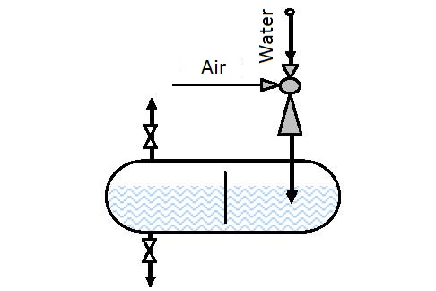 |
| Figure 14.1 Actual aeration under pressure |
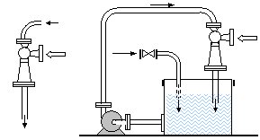
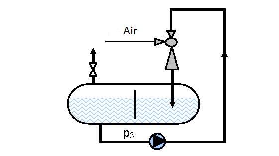
is performed with one or more serially connected ejectors. Clip aeration (figure 14.2 and 14.3) is performed by circular circulation processes. Underground aeration is performed by injecting water enriched with oxygen into underground water. Using ejector aerators ozone, pure oxygen, chlorine, and other gaseous and grain-like-powdery materials can be added that are used in water purification technology.
Ejector aerators operate on the same principle as other ejector devices. They use the energy of input fluid for operation (water or compressed air). The driving fluid (water or air) enters at great speed in to the ejector chamber where it collides and mixes with the pumped fluid (air or water). Due to different flow rates of the driving and pumped fluids both fluids break up into the smallest particles with large interacting surfaces. The large interacting surfaces lead to fast energy exchange and fast absorption and air (oxygen) solution. Dissolved oxygen reacts with iron and manganese making salts that settle and remain at the vessel or channel bottom. Ejector introduction of air performs blowing through of the polluted liquid that partially removes methane, ammonia and other gases.
 |
|
| Figure 14.2 In line and recirculation aeration | |
 |
|
| Figure 14.3 Circular-circulation aeration under pressure | |
Processes of gas solution in liquids can be divided into two groups: processes that require introduction of as much as possible gas (chlorination, ozoning, treatment of waste water etc.) and processes that require gas introduction until a saturated solution is reached (fishery and oil aeration).
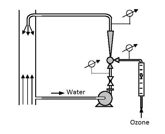 Figure 14.4 Ozoning drinking water
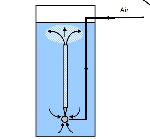 Figure 14.5 Ejector pneumatic hydro lift
Increase of the solution rate of oxygen can be attained by increasing the oxygen content in the pumped in air by moving air over zeolite filters etc.The gas solution rate in liquids depends on the mechanism of mass transfer between particles and gases. In an immobile environment molecular diffusion occurs very gently, so that complete solution saturation requires a long period of time. In a mobile environment the solution rate increases due to mass transfer in the mixture movement direction (convention) and turbulent flowing leads to the influence of pulsation causing turbulent diffusion.
Gas solution increases with the pressure increase and temperature decrease (see Ejector compressors and Ejector absorbers).
In continual processes liquid is moved over one or more serially installed ejectors.
In the clip procedure aeration is performed by circular-circulation movement through the ejector enabling complete saturation of the solution. Water from the aerator that contains part of the pumped in and un-dissolved air (oxygen) is ejected through perforated parallel or circulatory placed pipes. This method of distribution of the water-air mixture achieves more efficient mixing and faster saturation in the complete aeration space.
14.1 Ejector hydro-aerators
Water is used as the fluid in these aerators. They are used for flows up to several hundred m3/h for different temperatures and small and relatively high output pressures. The air/water volume ratio is within the 0-3 limits.
In fisheries ejector hydro-aerators can be used besides aeration for mixing deeper colder water with warmer surface water, antibiotic dosage, depth introduction of grain and powder food, depth dosing of limestone etc.
14.2 Ejector gas aerators
Gas aerators use compressed air for drive and polluted water as the pumped in fluid. These aerators are used when it is necessary to introduce relatively large amounts of air. They are used for small and large flows, different temperatures and not very high output pressures. More efficient mixing and faster saturation of the solution with oxygen can be attained using an ejector pneumo-hydraulic lift (figure 14.5).
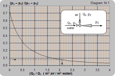 |
Data: The water pressure at the ejector input is p1= 4 baraps (3 bar), the pressure at the ejector output is p3 = 1,24 baraps (0,24 bar). Air pumping is performed from the atmosphere p2 = 1 baraps.
How much air can be pumped in with one cubic meter of water?
Solution: (p3–p2)/(p1–p2) = (1,24–1)/(4–1) = 0,08.
From the diagram one can read Qvaz/ Qvode = 2,1. For the given conditions 1 m3 of water will pump in 2,1 m3 of air.
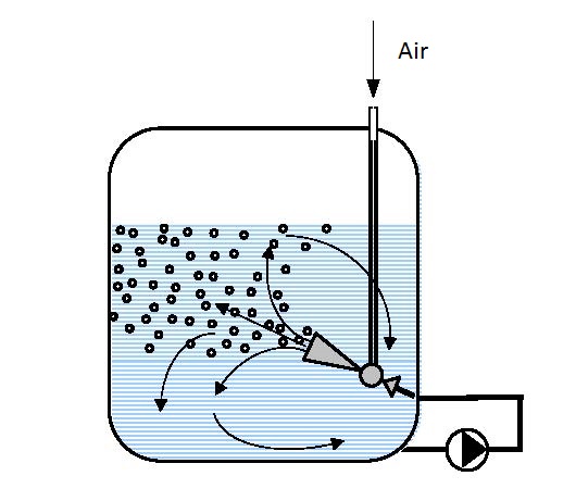 Figure 14.6 Clip aeration
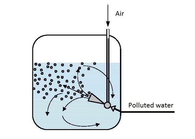 Figure 14.7 One pass aeration
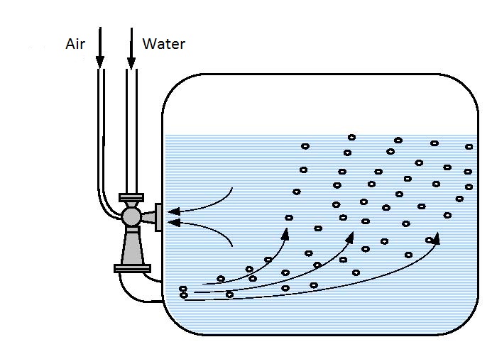 Figure 14.8 Combined aeration
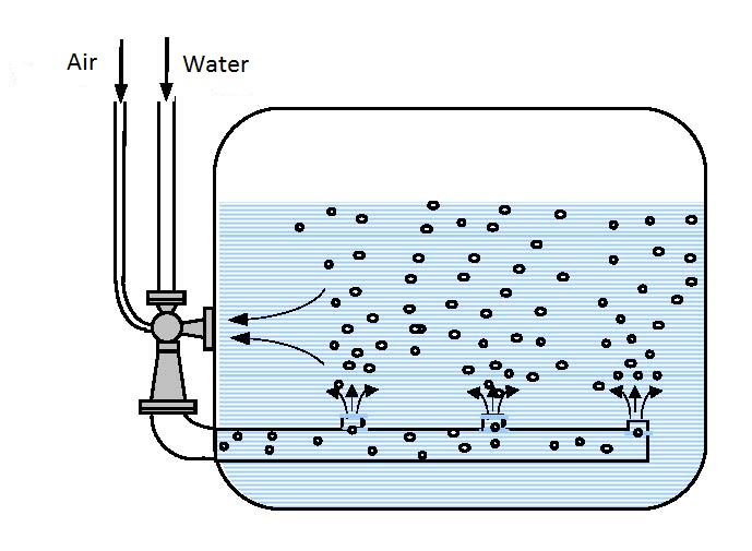 Figure 14.9 Combined aeration
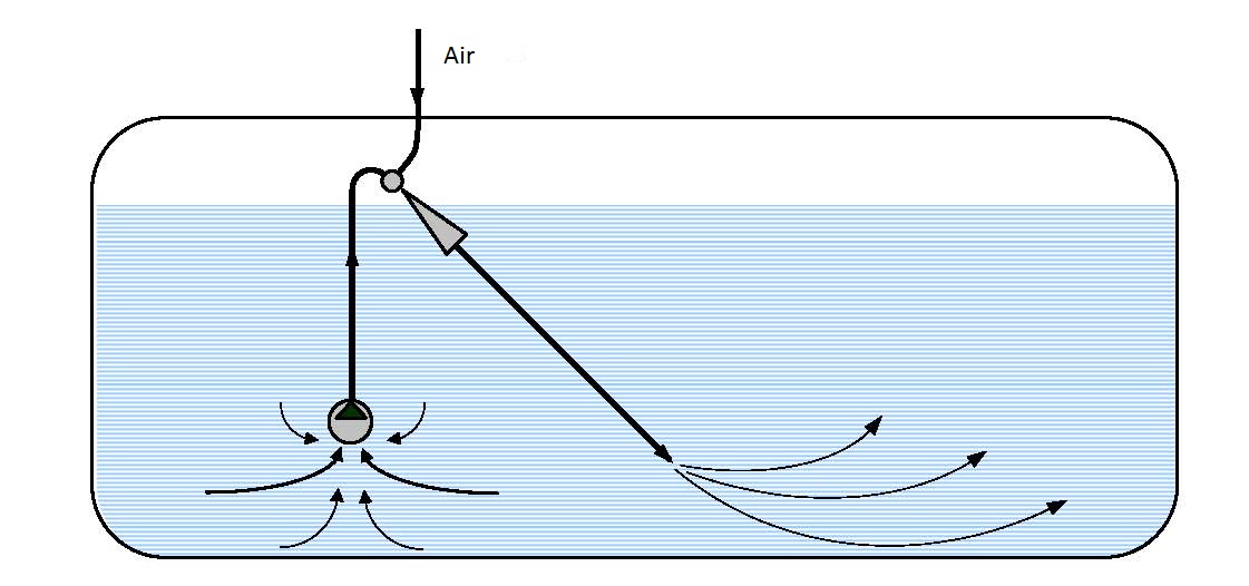 Figure 14.10 Clip aeration
2/11/2015
From underground water in ejector installations.
Distilled water is obtained by destillation (heating by boiling, evaporation and condensation) from surface, water main or well water. There are no dissolved minerals or other admixtures in distilled water so as the chemically and mechanically purest water it is used in the food, pharmaceutical and many other chemical processes requiring clean water.
Large amounts of distilled water are used in the production of:
- alcoholic beverages,
- bear,
- antifreese,
- accumulators,
- and for filling steam boilers etc.
The simplest and most economical solution for obtaining distilled water is from thermal sources in ejector installations. Production of distilled water from underground hot water in an ejector installation represents a novel original solution, that for a small investment enables a large and cheep production. The installation capacity depends only on the temperature and amount of thermal water available.
Operating principle:
Warm water, from the spring, is brought via a pipeline to a vessel (evaporator). Introduction of hot water whose vapor strain (evaporation pressure) is higher than the absolute pressure in the vessel leads to sudden evaporation of part of the introduced water. The heat needed for evaporation is taken from the remining water thus cooling it until an equilibrium state is established between the temperature and pressure.
The evaporated water is puumped in and removed by the ejector, while part of the remaining cooled water is removed via an overflow into the surrounding area. The driving water when entering the ejector chamber comes into contact with the evaporated water from the evaporator, mixes with it, condenses it and takes it into storage reservoirs. The remaining part of water cooled to t< 400°C is removed from the evaporator via an overflow vessel into the environment.
Such an installation does not pollute the environment, but returns partially cooled water to the riverbed, i.e. returns water with a lower temperature that is an ecological improvement.
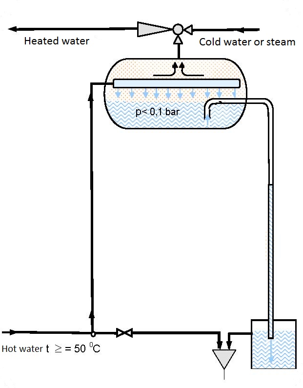 |
| Figure 13.1 Scheme of an installation for obtaining destillate from thermal underground waters |
Production of distilled water from underground hot water using an ejectr installation has a series of advantages in relation to all other existing solutions:
- cheaper price per production unit,
- investment savings,
- savings in consumed heat and electric energy per production unit (thermal water does not need to be heated),
- maintenance savings (do not require lubrication),
- workforce savings,
- the installation is ecologically completelly clean and does not pollute the environment,
- production can be completely automated and performed 24 hours a day all year round.
2/11/2015
Ejectors are widely applied in processes of gas and liquid mixing, in the field of chemical technology and many other technical branches.
All ejector mixing of gas and liquid can be divided into two groups.
The first group: includes ejectors that require pumping in as large amounts of gas per unit liquid flow as possible, where gas solution in the liquid is of no significance.
Such processes are used in ozoning, chlorinating and other devices, for compression of gas using liquids (see Ejector hydro compressors) and ventilation (see Ejector hydro ventilators).
The second group: includes ejectors of which gas solution and complete solution saturation is required. These processes are required in flotation, aeration, for cleaning liquids of oil products and other processes.
Gas solution in liquid is determined by Henry’s law:
m = k·p·Q. where:- - m – the mass of dissolved gas,
- k – the solution coefficient that depends on the type of gas and the temperature and liquid type,
- p – the pressure,
- Q – the liquid volume.
The formula shows that the amount of gas that can be dissolved into a liquid depends linearly on coefficient k, pressure p and liquid amount Q, meaning that in a certain liquid volume the amount of dissolved gas can increase by lowering the temperature or increasing the liquid pressure and vice versa.
The solution rate (mass transfer) depends on the mechanism of mass transfer between liquid and gas. In an immobile environment the mechanism of mass transfer is slow and occurs by molecular diffusion. In a mobile environment mass transfer intensifies in a current flow and in a turbulent flow turbulent diffusion occurs due to the influence of pulsation.
Air solution in water is usually not higher than several volume percents, so the pumping in volume coefficient is in the limits of:
q =Q2/Q1 = 0,1 – 0,15 where:- Q2 - volume flow of the pumped gas,
- Q1 - volume flow of the driving liquid.
Liquid under pressure p, passing through the ejector jet transforms the thrusting energy into kinetic (rate) energy. Liquid entering the ejector mixing chamber at a great speed catches and takes with it gas present in the chamber, thus forming a completely homogenous fine mixture. Due to different flow rates between the liquid and pumped gas, both fluids are broken up into the smallest particles. Such broken up and fine particle fluids have a large active interacting surface that enables a very fast mutual energy exchange (mechanical, chemical and heat and very fast absorption of pumped gas).
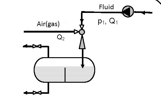 Figure 12.1 One pass liquid with open circulation
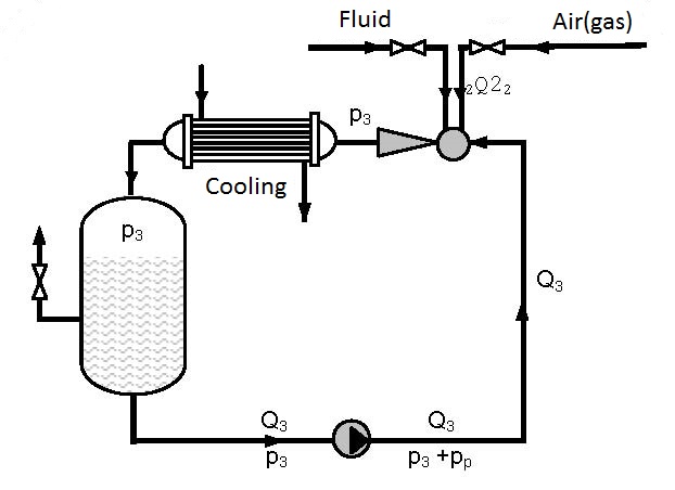 Figure 12.2 Closed circular circulation with cooling abilities
On the path of the current flow through the ejector gases dissolve very fast and solution saturation occurs in the tumultuous turbulent current. The fluid mixture (liquid with dissolved gas and un-dissolved gas) goes to the reservoir where separation of the un-dissolved gas takes place.
The simplest device for gas solution is presented in figure 12.1. Gas solution in liquids is achieved in one pass.
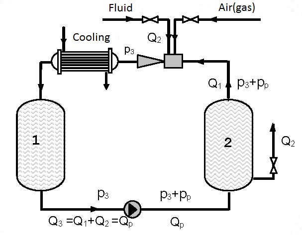
Figures 12.2 and 12.3 present devices with closed circulation, where higher pressures p3 for gas solution are achieved with the same pump (see diagrams 12.1 and 12.2).
On figure 12.2 gas solution is performed under pressure p3 that is higher than the pressure p3 on figure 11.1 as the driving liquid enters the ejector under pressure p3+pp, so the pressure at the ejector output p3 for the same working conditions is higher (see diagrams 12.1 and 12.2). Gas solution can be increased by cooling the gas-liquid mixture at the ejector output.
 Q2/Q3 (m3air / m3flow pump for Figure 12.1 and 12.2
 Q2/Q3 (m3air / m3flow pump for Figure 12.3)
As the amount of gas pumped in by the ejector and dissolved is small (q0 = Q2/Q1 = 0.1-0.15) in the first approximation the assumption can be made that a single phase fluid i.e. liquid is circulating. Figure 12.3 shows a device in which gas is dissolved in a thrusting ejector pipeline and reservoir 1 under pressure p3 and after passing through the pump solution is performed in the thrusting pump pipeline and reservoir 2 under pressure p3+pp.
Devices constructed according to figures 12.2 and 12.3 enable significant improvement of the utilization degree compared to single pass pumps and ejectors (figure 12.1). Increase of the utilization degree proportionally increases the amount of dissolved gas. The amount of dissolved gas, according to figures 12.2 and 12.3, can be several times higher than the amount of dissolved gas according to figure 12.1. The process can be discontinuous and continual. In a continual process liquid and gas are introduced at the same time as is shown in figures 12.2 and 12.3.
Diagram 12.1 shows the dependence between the pressure ratio p3/pp on the ratio between the volume flow of the pumped air and pump flow Q2/Qp. The diagrams are valid for pumping atmospheric air and pressures p3 and pp are given in bars.
Diagram 12.2 shows an estimated curve of the dependence of the pressure ratio on the flow ratio. As the amount of air pumped in is small it is disregarded so Q2 only represents the liquid flow.
The maximal ratio of manometer pressures p3/pp (bar/bar) that can be attained for Q2 = 0 is:
- for connecting according to scheme 12.1 p3/pp = 0.7
- for connecting according to scheme 12.2 p3/pp = 2.5
- for connecting according to scheme 12.3 p3/pp = 3.5
In the range practically most interesting and most often used the pumping coefficient q = 0.1-0.15 is enough to provide air (gas) for complete liquid saturation.
Example 12.1According to schemes 12.1 and 12.2 how much atmospheric air (pair = 1 barabs) can be pumped with pump pp = 5 bar and flow Qp = 10 m3/h and put into a reservoir where the pressure is p3 = 3 bar?
Solution: For the pressure ratio p3/pp = 2/5=0.4 diagram 12.1 reads:- for the installation according to figure 12.1 Q2/Qp =0.3 and Q2 = 0.3×Qp = 0.3×10 = 3 m3air/m3water,
- for the installation according to figure 12.2 Q2/Qp =0.6 and Q2 = 0.6×Qp = 0.6×10 = 6 m3air/m3water.
| Figure 12.3 Closed circular circulation with possible cooling |
2/11/2015
Hydrogenization is one of the most applied procedures in organic synthesis and in industrial applications it is the most used reaction. The hydrogen molecule can enter the reaction faster with more functional groups from any other molecule. Hydrogenization compared to alternative methods for reduction is the most economic. When viewing general trends in hydrogenization technology it can be established that greater attention is being paid to:
- optimization of development laboratories and semi-industrial research,
- increase in economy,
- improvement of safety of operation and the environment.
The stated development trends are most efficiently fulfilled using reactors with circulatory flow and an ejector mixer. These types of reactors are applied more widely in many chemical processes, but are most often used for hydrogenization.
The operating principle of a filling hydrogenization procedure using ejectors is given in figure 11.1. The starting material (can be dissolved in a solute or not or in the form of a fine solid catalyzer) is pumped in from the reactor and then via a heat exchanger (if heating or cooling is needed) and ejector is put back into the reactor forming a circular circulation.
When passing through the ejector nozzle the rate of the reaction suspension increases so it enters the chamber at a great rate. In the ejector chamber particles of the reaction suspension collide with the gas particles present (hydrogen) and both fluids are reduced to the smallest particles forming a completely fine homogenous mixture.
The reduced fine particles of both fluids have a large active touching surface that enables fast energy exchange (mechanical, heat and chemical) and depending on the fluid type a relatively fast reaction, i.e. absorption.
The formed gas and suspension mixture is thrusted out of the ejector into the reactor space filled with the suspension. The undissolved, i.e. unreacted excess hydrogen (gas) after leaving the ejector lifts to the suspension surface in the gas area of the reactor fr4om where it is pumped in again by the reactor.
Experiments have established that the ratio between the surface mass transfer and reaction volume per energy unit (m2/m3) is two times higher than the one reached in a reactor with a turbine mixer, thus significantly increasing the reaction rate.
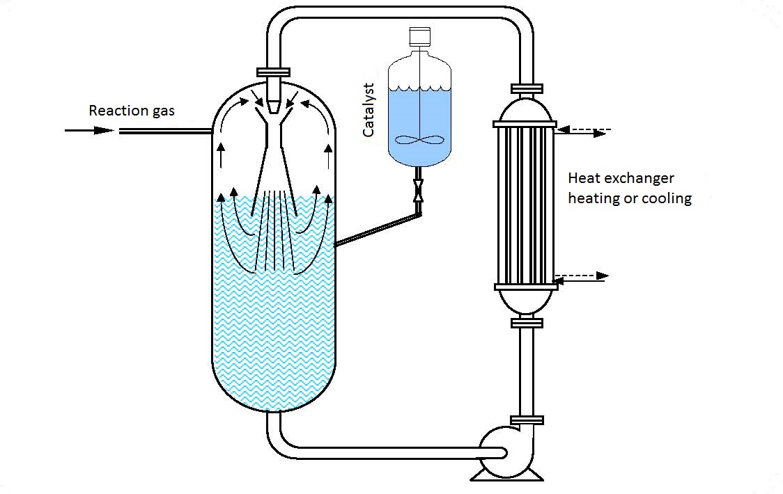 |
| Figure 11.1 Hydrogenization |
In a reactor with a circular flow the degree of gas-liquid mixing is constant during the reaction that has a significant influence on shortening the time required for the reaction and also reduction of the energy utilized per production unit.
A great advantage of a circular reactor is that the heat exchanger is installed outside the autoclave so there are no dimensional limitations. Selection of a corresponding exchanger size with a large heat transfer coefficient enables fast removal or conveyal of heat necessary for the reaction.
A system of automated temperature control enables maintenance of the reaction temperature with a precision higher than ±1oC. Such a system enables maintenance of a homogenous mixture during the whole mixing time.
A combination of a fast reaction rate and precise temperature control in most cases leads to the best possible yield and prevention of side reactions. Due to the more intensive and shorter mixing time and uniform catalizer distribution, the percentage of the catalizer introduced into the reaction is reduced for 30-50% and more in some cases, so its total consumption is reduced.
Circular reactors with an ejector have a series of advantages compared to reactors with mixers and they are:- high removal and conveyal heat rate,
- lower catalyzer use, per production unit,
- faster reaction,
- savings in driving energy of mass transfer and thus a shorter working cycle,
- no mixer requiring large driving engines and a strong construction,
- ejectors have no mobile parts so do not require lubrication and maintenance,
- ejectors can relatively easily be installed and put into operation indenepndently of a mixer or work in parallel with the mixer,
- the process can easily be automated, with a precise temperature control enabling a physically easier, safer and secureroperation.
Hydrogen catalytic hydrogenization is applied in the production of cooking oil, chemical industry or organic intermediaries, dyes, solutions, agrochemistry, pharmacy and many other technological processes.
The standard reactions applied are:- heterogeneous catalytic hydrogenization,
- acryling,
- nitrilation,
- phosgenization,
- amilation,
- chlorination,
- carbonization,
- etoxilation and
- many other reactions.
An ejector can additionally be installed in many existing reactors with mixers and it can work in parallel with the mixer or independently. Ejector installation is simple and does not require any changes in the existing reactor.