EJECTOR COMPRESSORS Division
Depending on the type of driving fluid ejector compressors are divided into:
Operating principle:
All ejector compressors operate on the principle of using high pressure energy of the driving fluid for pumping in and compressing pumped gases. The pressure of the fluid mixture at the ejector output depends on the input pressures of the driving and pumped fluid and their mass flow ratio.
6.1 Ejector hydro compressors (liquid-gas)
Liquid, most often water is used as the driving fluid for these compressors for pumping in and compressing gases (most often air). Depending on the pressure of the driving liquid and mass ratio between the gas-liquid flow it is possible to compress gases to pressures higher than 10 bars. The volume ratio between the gas-liquid flow can be realized within the limits of 0 – 3 (Vg/Vt, [m3/m3]).
Compressed gas exiting the ejector is practically washed and partly cleansed from various pollutants. This compression procedure practically removes dust and other mechanical pollutants from gas and also droplets and evaporates of other liquids (water, oil, etc.).
Application:
They are used for compression of gas requiring relatively low flows and large pressures (for example ozoning drinking water, figure 6.1), pumping in compressed air into a hydrofor (figure 6.2) and many other processes.
They are especially applied in the food industry that requires clean compressed air with no dirt and compressed oil content. The relative moisture of such compressed air is close to 100% that is also desirable in the food industry.
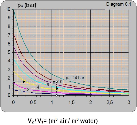
Diagram 6.1 shows the dependence between the output pressure p3 on the pump input pressure p1 = pp and the volume ratio between the pumped in air and water V2/V1.
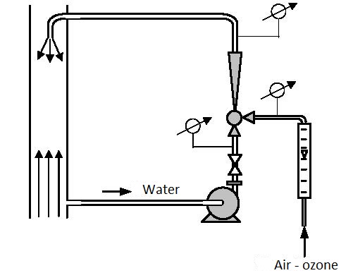
Figure 6.1 Ozoning of drinking water
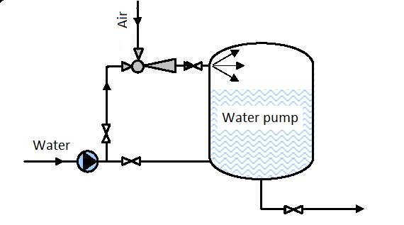
Figure 6.2 Pumping air into a hydrofor
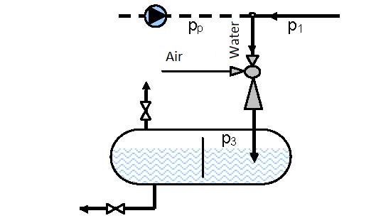
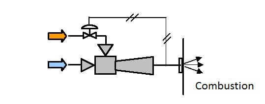
Figure 6.3 Open system for air compression
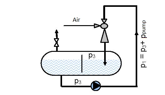
Figure 6.4 Circulation (closed) system for air compression
Example 6.1
Data: Air using water needs to be pumped in a vessel (figure 6.3) under pressure p3 = 1.6 bar. The pressure of driving water in front of the ejector is p1 = 10 bar.
How many cubic meters of air can be pumped in with one cubic meter of water?
Solution: For the reservoir pressure of p3 = 1.6 bar and water pressure in front of the ejector of p1 = 10 bar, from diagram 6.1 one reads that V2/V1 = 1.1 that means that 1.1 m3 of air can be pumped in with 1 m3 of water.
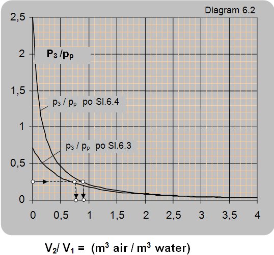
Diagram 6.2 shows the dependence of the ratio between manometer pressures at the ejector output and pump pressure p3/pp on the ratio between the volume flow of air and water, for operating conditions presented in figures 6.3 and 6.4.
The maximal pressure that can be reached in the vessel according to the connection scheme presented in figure 6.3 is 0.7 of the driving pressure of pump pp, i.e. pipeline pressure p1 (p3 =0.7×p1 = 0.7×pp) and according to the connection scheme given in figure 6.4 is 2.44 times the pump pressure pp (2.44×pp)
Example 6.2
Data: The pressure ratio between the reservoir and pump is p3/pp = 0.25. The flow for the connection schemes given in figures 6.3 and 6.4 is required?
Solution: For the pressure ratio of p3/pp = 0.25 the volume flow ratio is read from figure 6.3 as V2/V1 = V2/Vp = 0.75 and according to figure 6.4 V2/V1 = 0.9.
6.2 Ejector gas compressors
These compressors are used for mixing and compressing gases. Compressed gas (most often air) is used as the driving fluid for these compressors. It is used for pumping, mixing and compressing the pumped gas. Using the Laval nozzle the output rates of the driving gas rise to speeds above the speed of sound, so they can be efficiently used for attaining relatively high output pressures.
 |
| Figure 6.5 Mixing combustible gas and air |
Application:
They are used for extraction of natural undergoing gases with low pressure using other or similar gases present at higher pressures, for mixing compressed gases with different pressure in order to obtain a mixture with a corresponding pressure, for obtaining gas sinter under very high pressures (several hundred bars), for example for obtaining ammoniac.
Figure 6.5 shows the scheme of pumping, mixing and compressing combustible gas and air.
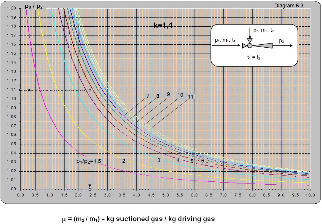
Diagram 6.3 shows the dependence of the ratio between the absolute pressure of the driving and pumped fluid (p1/p2) on the ratio between mass flows (m2/m1) for t1 = t2. The diagram can be used for different temperatures t1 and t2 though the read values of m must be multiplied with (T1/T2)0.5 (T1 and T2are absolute temperatures of the driving and pumped gas).
Example 6.3
Data: The driving pressure at the ejector input p1 = 4 barabs, pumped pressure p2 = 0.9 barabs, pressure at the ejector output is atmospheric p3 = 1 barabs. What is the mass flow ratio?
Solution: For t1 = t2 and pressure ratios p1/p2 = 4/0.9 = 4.4 and p3/p2 = 1/0.9 = 1.11. From diagram 6.3 m = m2/m1 = 2.4.
 |
6.3 Ejector vapor compressors
Saturated or pre-heated water vapor is used as the driving fluid for these compressors. Driving vapor, passing through the nozzle expands to very low pressures and enters the ejector mixing chamber at the speed of sound or higher. In the mixing chamber particles of the driving liquid are taken up, compressed and take along vapor from the inlet port. The ratio between the output and input pressure is 1-10. Higher values are related to low pumping pressures of 0.01-0.1 barabs.
Application:
Using fresh vapor as the driving fluid it is possible to pump in and compress used vapor and return it back into the process. Ejector vapor compressors are used in the following processes:
- evaporation,
- cooling,
- crystallization,
- dezoxidation,
- degasification,
- drying,
- for compression of evaporated condensed water vapor and – coupler evaporate.
Figures 6.4-6.8 give schemes of some processes that use ejector compressors.
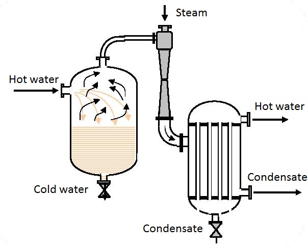
Figure 6.6 Heat pump (return of heat from excess hot water)
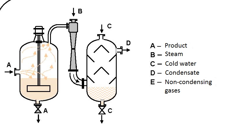
Figure 6.7 Vacuum crystallization
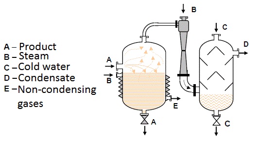
Figure 6.8 Deodoring
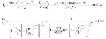
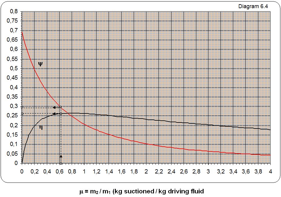
The diagram labeled y 6.4 marked the dependence relations 1 kg mass flow of energy mix at the exit from ejector and 1 kg mass flow driving energy at the entrance to ejector depending on the mass relations suctioned and drive the flow multiplied with the square root of the relationship of their absolute temperature y = (m2/m1)·(T2/T1)0,5.
The symbolic R, T and k marked the gas constant, absolute temperature and exponent adiabate process. Index 1 refers to the drive gas, the index 2 refers to suction gas, and the index 3 to the mix driving and sunctioned gas to exit from ejector. Label h indicated a coefficient of utility. Diagram 6.4 can be used for all types of gases and water vapor and for all temperatures.
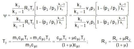
where is : T1,2,3 – absolute temperature of gas in idlea, R1,2,3 – gas constant.
Example 6.4
Data: With 1 kg of compressed air driving pressure p1 =11 baraps be suctioned 0,61 kg of air which is under pressure p2 =1,1 baraps.
Search is what you can get pressure on the exit ejector p3:
a) when the drive temperature and air usisavanog equal t1 = t2 and
b) when the air temperature driving t = 800 °C, and suctioned air t2 = 200 °C?
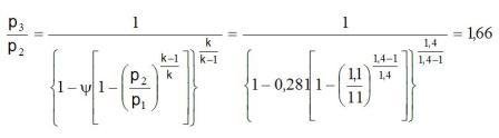
Solution: The ratio of the mass flow m = m2/m1 = 0,61/1 = 0,61 from diagram reading to y = 0,281 and the coefficient of usefulness m = 0,27.
a) How is the air k1= k2 = k3 i R1 = R2 = R3 it from the equation 6.2-1 za t1 = t2 gets
p3 = p2·1,66 = 1,1·1,66 = 1,83 baraps.
b) For m = 0,61 temperature at the exit from ejector is
p3 = 1,7287·1,1 = 1,9 baraps.
 |
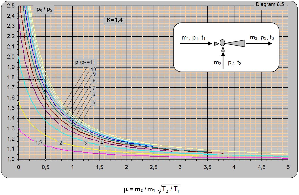 |
Diagram 6.5 for k = 1.4 gives the ratio between the absolute pressure at the ejector output and the pumped pressure (p3/p2) depending on the absolute pressure ratio between the driving and pumped air p1/p2 and mass ratio of the pumped and driving flow (m1/m2). Diagram 6.5 is given for conditions when the driving and pumped gas have the same adiabatic exponent k = 1.4 and temperature t1 = t2. The diagram can be used for different temperatures of the driving and pumped gas by multiplying the value of m from the diagram with
(T1/T2)0,5 [m = (m2/m1)·(T2/T1)0,5].
Thus, for the same operating conditions, a temperature increase of the driving gas will increase the amount of pumped gas and vice versa. T1 denotes the temperature of the driving gas and T2 denotes the pumped gas temperature.
Ejectors that use compressed gas (air) for drive can be used for extraction and separation of water vapor and other evaporates.
Example 6.5
Data:Air present in a vessel under pressure of p2 = 1.4 barabs and temperature t2 = 200oC should be pumped in and compressed to a pressure of p3 = 2.45 barabs. Air under pressure p3 = 12.5 barabs and temperature t1 = 200oC is used to drive the ejector. How many kilograms of air can be pumped in with 1 kg of driving air?
Solution: For pressure ratios p3/p2 = 2.45/1.4 = 1.75 and p1/p2 = 12.5/1.4 = 8.93 from diagram 6.5 [m = (m2/m1)× (T2/T1)0.5 = 0.51. With 1 kg of driving air about 0.51 kg of air can be pumped in from the vessel.
Diagram 6.6 for k = 1.135 (saturated water vapor) shows the ratio between the absolute pressure at the ejector output and the pumped pressure (p3/p2) depending on the absolute ratio between the pressure of the driving and pumped water vapor p1/p2 and mass ratio of the pumped and driving flow (m2/m1). Diagram 6.6 is valid for conditions when the driving and pumped vapor have the same adiabatic exponent k = 1.135 and the same temperature t1 = t2. The diagram can be used for different temperatures of driving and pumped water vapor, but the value of m read from the diagram must be multiplied by (T2/T1)0.5. From this follows that, for the same operating conditions, with increase in the temperature of the driving vapor the amount of pumped vapor will be higher and vice versa with increase in the temperature of pumped vapor the amount of pumped vapor will be lower. T1 denotes the temperature of the driving and T2 of the pumped water vapor.
Diagram 6.7 for k = 1.3 (saturated water vapor, gases, and all who have K = 1.3) shows the ratio of absolute pressure at the exit from ejektora and usisavanog pressure (p3/p2) depending on the relationship of absolute pressure and driving usisavane steam p1/p2 and mass relations usisavanog and driving the flow (m2/m1). Diagram 6.7 is given for conditions when the driving and usisavana pairs have the same izložitelj adijabate k = 1.3 and the same temperature t1 = t2. Diagram can be used for different temperatures and driving and suctioned steam which, in the diagram guest value of m should be multiplied by (T1/T2)0.5. From here it follows that, in the same conditions, with increasing temperature steam drive sunctions the greater the amount of steam sunctioned and vice versa, or with increasing temperature sunctioned staeam sunction the smaller amount of steam sunctioned and vice versa. The T1 is a marked temperature driving, and with T2 sunctioned steam.
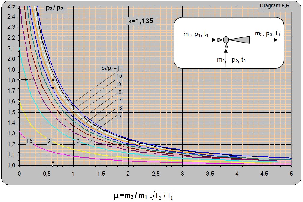 |
Example 6.6
Data:The pressure of saturated pumped vapor of p2 = 1.1 barabs and temperature t2 = 102.32oC needs to be compacted to p3 = 2 barabs.
How many kilograms of pumped vapor m2 can be pumped with m1 = 1 kg of driving vapor if the pressure of driving saturated vapor is p1 = 11 barabs and the temperature is t1 = 184.07oC?
Solution: For k=1.134 and p3/p2 = 2/1.1 = 1.81 and p1/p2 = 11/1.1 = 10 m = (m2/m1)× (T2/T1)0.5 =0.61 is read from diagram 6.6. Due to unequal temperatures T11T2 of the driving and pumped vapor a correction will be made so m2/m1 = m×(T1/T2)0.5 = 0.61×[(273+184.07)/(273+102.32)]0.5 = 0.67.
For the set conditions with m1 = 1 kg of driving vapor m2 = 0.67 kg of vapor can be pumped.
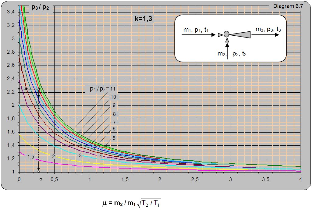 |
Example 6.7
Data:With a driving pressure of pre-heated vapor p1 = 18 barabs and temperature t1 = 2800oC one needs to pump in preheated vapor with a pressure of p2 = 2 barabs and temperature t2 = 1600oC and compress it to a pressure of p3 = 4.5 barabs. What is the mass flow ratio m2/m1?
Solution: For pressure ratios p3/p2 = 4.5/2 = 2.25 and p1/p2 = 18/2 = 9 on diagram 6.7 m = (m2/m1)× (T2/T1)0.5 = 0.29. The mass flow ratio is m2/m1 = m×(T1/T2)0.5 = 0.29×[(273+280)/(273+160)]0.5 = 0.33.