One of the most significant tasks of centrifugal pumps is operation in wide pressure and flow ranges. Regulation of pressure and flow is performed only in regions defined by Q-H pump curves.
The classical method of exchange of working points of centrifugal pumps is performed by muffling. Muffling is also used for pump protection from overload that can occur when pumps operate at low pressures.
This type of regulation loses part of the energy and reduces the pump utilization coefficient.
In practice requests that exceed capabilities of serial pump type characteristics often occur.
One of the ways of a wider correction of pump working characteristics is connecting pumps to ejectors. Pumps connected with ejectors can be used for flow or pressure increase. Q-H curves of aggregates (pumps connected with ejectors) are presented on diagram 1.2.
The connection of ejectors and centrifugal pumps significantly extends the application field of pumps and enables the construction of autonomous devices for different applications.
Connecting pumps with ejectors enables a flow increase on account of reduced pressure, i.e. pressure increase on account of reduced flow.
Suitable connections of pumps and ejectors enable aggregate operation at a high utilization degree h=0.8 (see diagram 1.2).
Ejectors connected with pumps enable:
- Change of working characteristics of centrifugal, axial, spiral and other types of pumps in a wide range (diagram 1.2, figure 1.5 and 1.6).
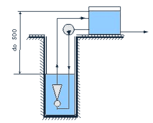
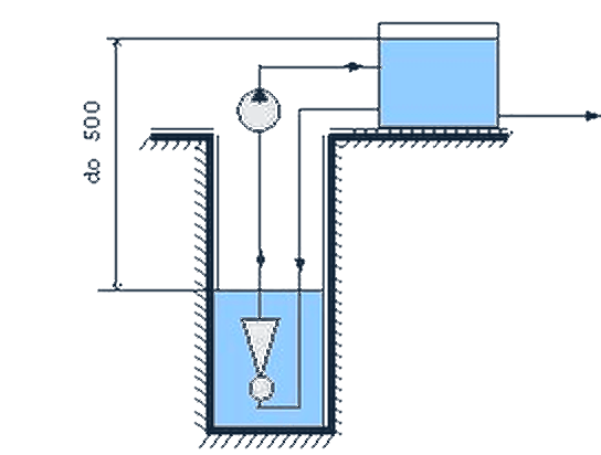
- Pumping liquids from deep wells, grids, probes and other deep holes (figure 1.6).
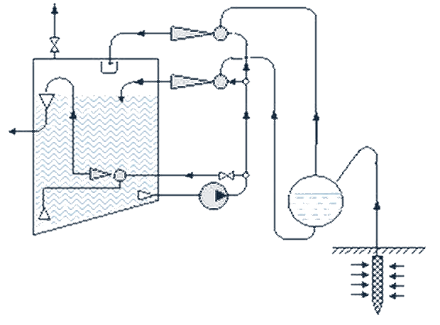
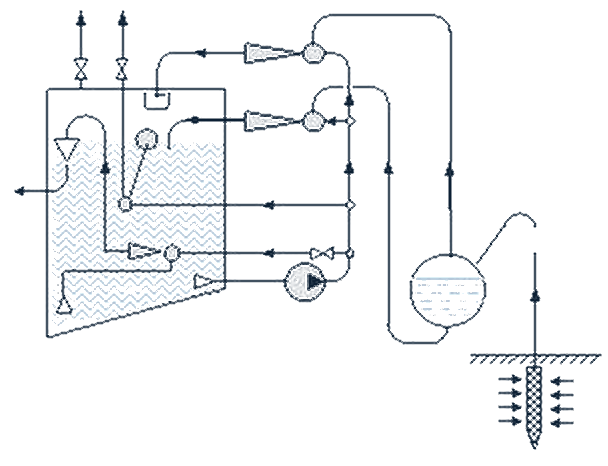
- Pumping liquid containing gas (figure 1.7 and 1.8).
- Establishing the required vacuum for draining, drying and reducing levels of underground water, drainage in construction (figure 1.9 and 1.10).
- Increasing the allowed pumping height of centrifugal pumps and increasing the cavitation reserve when working with warm, hot and easily evaporable liquids (figure 1.11 and 1.12)
- Removing air and other gas from input pipelines and other cavities, starting pumps that do not have a self-pumping capability, and also constant maintenance of submerged pumps, enabling an easy and fast start-up (figure 1.7, 1.8 and 1.10).
- Pumping gaseous, corrosive, poisonous, aggressive, inflammable, explosive and other dirty and polluted liquids from places difficult to access.
- Hydrotransport of mud, sand, slag and other mixtures of liquid and solid grain-like and crushed materials.
- Mixing and solution of different liquids and gases; aeration, absorption, chemical reactions etc..
- Extraction of explosive, inflammable and polluted gases.
- Air compression.
- Providing high vacuum.
1.1 Pump aggregates for changing working characteristics of a pump
The way a pump is connected to an ejector depends on the set working conditions. In practice combinations shown in figure 1.4 and 1.5 where pumps and ejectors are at approximately the same levels (same geodesic height) are most often met.
Open non-circulatory pump aggregate
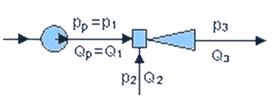
Figure 1.4 shows an open non-circulatory pump aggregate. For this connection pressure ratios depending on the flow ratios are given in diagram 1.1.
Closed circulatory pump aggregate
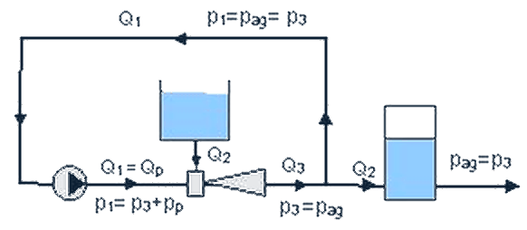
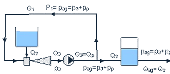
In a closed circulation device (aggregate) presented in figure 1.5a the aggregate flow Qag = Q1 with aggregate pressure pag = p3 is separated at the ejector output.
The aggregate flow Qag = Q1 goes into the hydrofor and then for further consumption, while the remaining flow Qp = Q1 with aggregate pressure pag goes via the pump into the ejector and then further into the circulation.
The pressure of pumped liquid entering the ejector, for ejectors installed under the level of the pumped liquid is p2 = + H2r2g and for ejectors above the level of the pumped liquid p2 = – H2r2g.
H2 denotes the height difference between the ejector axis and the level of the pumped liquid. For ejectors lying at the pumped liquid level H2 = 0 so p2 is also 0.
The scheme of a closed circulation aggregate presented in figure 1.5b is analogous to the previous one, but the aggregate flow (effective flow) Qag = q2 with aggregate pressure pag = p3+pp is separated at the centrifugal pump output. The effective (useful) flow is Qe = Q2 = Qag. The effective (useful) pressure represents the difference between the aggregate pressure and the pumped liquid pressure at the ejector input and it is:
pe = pag – p2 = p3 – p2 for the aggregate shown in figure 1.5a and
pe = pag – p2 = p3 – p2 + pp for the aggregate shown in figure 1.5b.
For aggregates shown in figure 1.5a and 1.6a the ratio between the effective (useful) flow and effective (useful) pressure and the pump flow and pressure is:
qa = Qe/Qp = Qag/Q1= Q2/Q1 = m
ψa = pe/pp = (p3–p2)/(p1–p3)
For aggregates shown in figure 1.5b and 1.6b the ratio between the effective (useful) flow and effective (useful) pressure and the pump flow and pressure is:
qb = Qe/Qp = Qag/Qp = Q2/(Q1+Q2) = μ/(1+μ)
ψb= pe/pp = (p3–p2+pp)/pp= 1+(p3–p2)/(p1–p3) = 1+ψa
Example 1.3 (figure 1.5a)
Data: The ejector is 1 m below the pumped water level so p2 = 0.1 bar. The pressure at the ejector output is p3 = 4 bar. The pump flow is Qp = 10 m3/h and the required aggregate flow is Qag = Q2 = 5.5 m3/h. Determine the pump pressure?
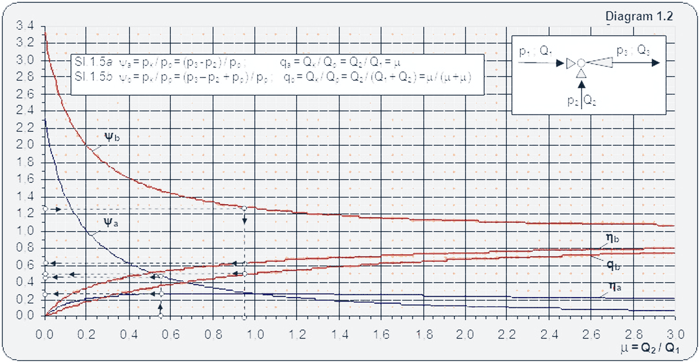
Solution: For the flow ratio m = Q2/Q1 = Qag/Qp = 5.5/10 = 0.55 from diagram 1.2 one can read
ηa = 0,29; i ψa= 0,48
pp = (p3-p2)/ψa= (4-0,1)/0,48 = 8,125 bar.
Example 1.4 (figure 1.5b)
Data:The effective (useful) pressure the aggregate needs to realize is pe = 4 bar. The pumped liquid needs to be raised to 40 m. A pump with pressure pp = 3.1 bar (31 m) and pump flow Qp = 10 m3/h is available. What is the effective flow-aggregate flow Qe = Qag = Q2 =?
Solution: From diagram 1.2 one can read
ψb = Hag/Hp = 40/31 = 1,29; μ = 0,95: ηb= 0,62: qb = 0,51
The effective (useful) flow
Qk= Q2 = qb·Qp = 0,51·10 = 5,1 m3/h.
Figures 1.5a and 1.5b show closed circulation aggregates with pumps and ejectors installed on the ground level at the same height (above sea level).
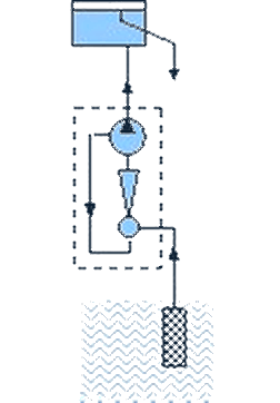
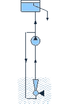
Figures 1.6a and 1.6b show closed circulation aggregates with ejectors installed below the pump level and submerged into the pumped liquid.
Diagram 1.2 presents the dependence between the pressure and flow ratios. Curves indexed with a refer to figures 1.5a and 1.5b, while index b refers to figures 1.6a and 1.6b.
For aggregates in figures 1.5a and 1.5b for a completely closed flow Qe = Qag = Q2 = 0, m = Q2/Q1 = 0, the effective (useful) pressure pe is 2.3 times higher than the pump pressure (curve ya = pe/pp = 2.3), while for aggregates in figures 1.6a and 1.6b the effective pressure is 3.3 times higher than the pump pressure (curve yb = pe/pp = 3.3).
Depending on the change in pressure ratio the flow ratio will also change (Qe/Qp) as can be seen on diagram 1.2.
1.2 Pump aggregates for extracting liquid from deep wells
In practical application of pump extracting stations there is a need to extract liquids from depths significantly higher than the allowed pumping heights of centrifugal pumps. Various types of depth pumps are used in such conditions. Installation, maintenance and servicing of such pump types are very expensive and their lifetime is short. Such pumps cannot be used for liquids that have a high temperature and contain gases and solid particles. Pump aggregates with centrifugal pumps and ejectors are devices that are most suited to such conditions.
Aggregates for which centrifugal pumps are installed at ground level and ejectors lowered and submerged into the pumped liquid are shown in figures 1.6a and 1.6b and their characteristics are given in diagram 1.2
1.3 Pump aggregates for providing levels for self-pumping and pumping liquids containing gases, sand and other admixtures
Self-pumping pumps and pump aggregates are essential in many fields of industry, construction engineering, water power engineering, melioration work, reducing underground water and other specific operating conditions. Based on research it was established that gas content in the pumped liquid above 5-7% significantly reduces the pump utilization coefficient and can lead to cessation of liquid flow through the pump. For this reason it is much more acceptable and useful to use coupled pumps and aggregates. Aggregates in which centrifugal pumps are connected with ejectors enable maintenance of the required vacuum in complex conditions when the pumped water contains gases (air, methane etc.), sand and other gaseous admixtures sometimes in amounts larger than the pumped water (figures 1.7 – 1.10).
Such aggregates are widely applied in the river and sea fleets for extracting liquids from various ship cavities, in sewage pumping stations and everywhere where gases and solid particles appear in pumped water.
1.4 Pump aggregates for increasing the pumping height (strain above cavitation)
In order to provide normal operating conditions the pumping height must not be higher than the allowed height. In practice the following cases often occur, where the pumping height needs to be increased:
- when operating pumps in pumping stations with a high variation amplitude of the pumped liquid level;
- when operating pumps with a condensate and heated or overheated liquids with a high vapor voltage;
- when operating dosage pumps in thermal energy systems;
- when operating pumps with a high rotation number;
One of the methods for providing normal pump operating conditions is connecting pumps with ejectors as shown in figures 1.11 and 1.12.
All ejector types
Ejector mixers
Fast and completely homogeneous mixing of liquids, emulsions and suspensions – no moving parts, no agitators.
Read more →Ejector heaters
Direct heating of liquids with steam or hot water at 100 % heat utilisation.
Read more →Ejector coolers
Vacuum cooling of liquids, pastes, powders, fruit and vegetables – without refrigerants.
Read more →