General information, working principle, components and applications
EJECTORS (INJECTORS) or jet pumps belong to the family of jet machines. Based on our own theory, numerous experiments and long experience with many installed plants, the flow and geometric parameters of the ejectors have been optimised to secure operation at a high efficiency of η = 0.25 – 0.75. Several patents (including our own) with new original solutions have been registered in recent years, simplifying existing technological processes. Ejectors are well suited to automation with minimal occasional supervision.
See the interactive ejector anatomy with the operating animation on the home page. →
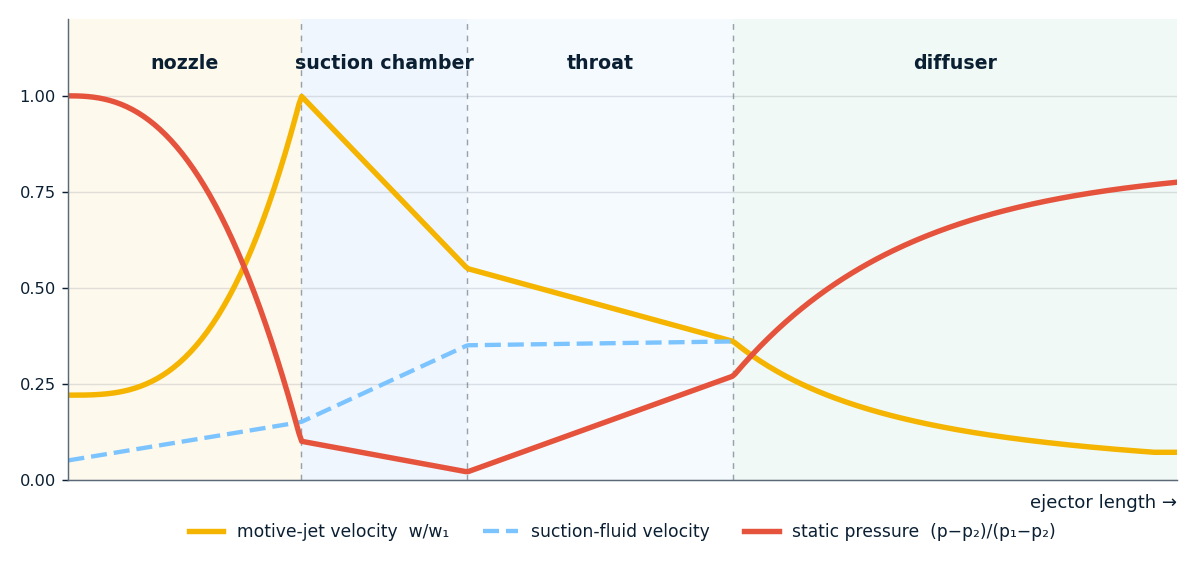
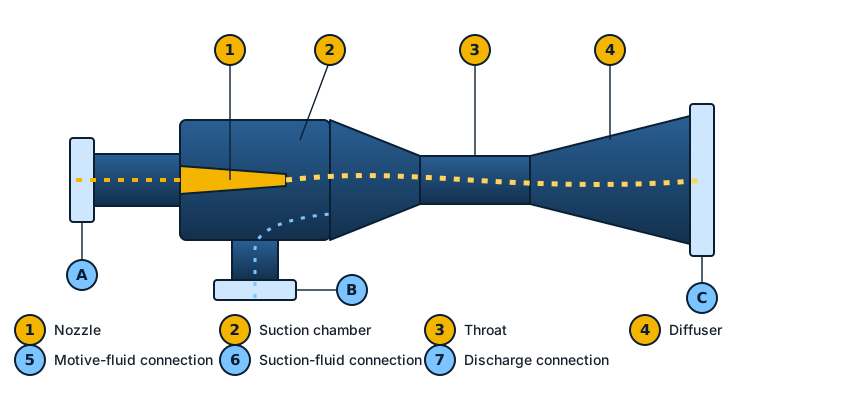
The motive fluid – liquid (emulsion, suspension), gas or steam – converts most of its pressure energy into kinetic energy while passing through the nozzle, forming a jet that enters the suction chamber at high (for gases and steam supersonic) velocity.
At the chamber inlet the motive-fluid particles meet the suction-fluid particles, collide and mix with them and carry them along. Owing to the different velocities both fluids are broken into the finest particles and a large active contact surface forms – a completely homogeneous mixture with rapid exchange of mechanical, thermal and chemical energy.
In the diffuser the flow area widens, the mixture slows down and the pressure rises up to the ejector outlet. The discharge pressure depends on the pressure and flow ratios of the suction and motive fluid and is always higher than the suction and lower than the motive pressure.
Dr Ljubomir Petrović, the founder of the company, defended his PhD thesis “Theoretical determination of optimal flow and geometric parameters of ejectors” at the Faculty of Mechanical Engineering in Belgrade in 1981.
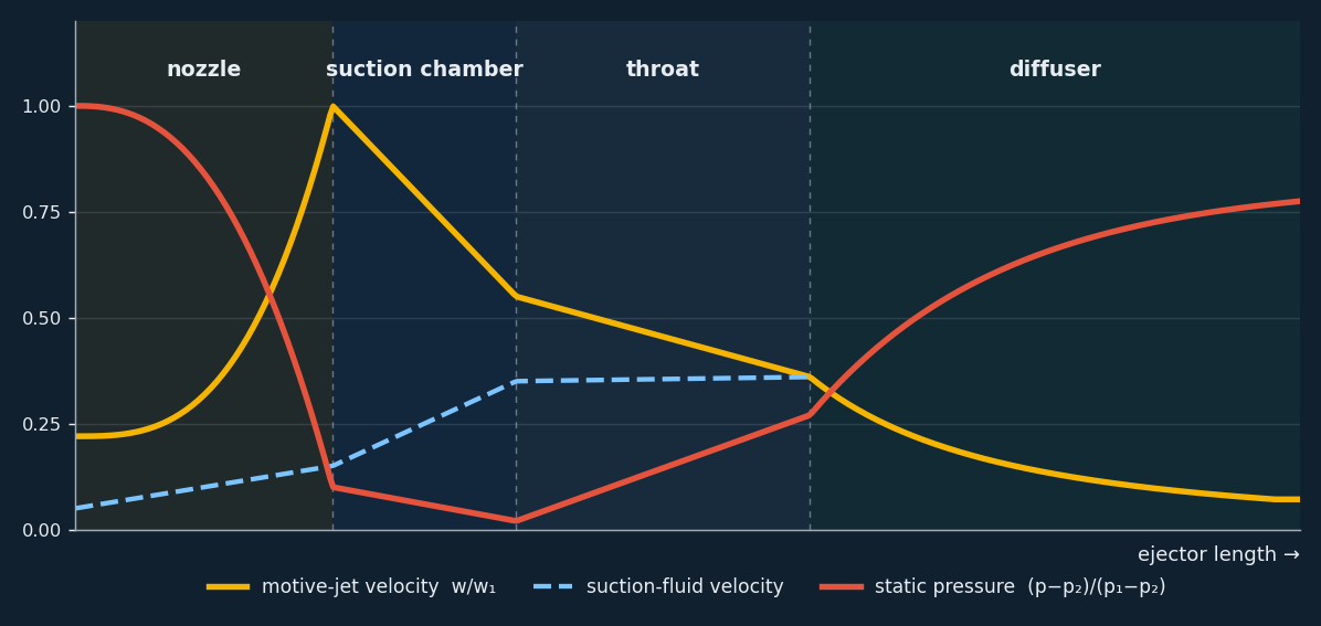
Qualitative change of the motive-jet velocity, the suction-fluid velocity and the static pressure from inlet to outlet. The pressure is lowest at the nozzle exit – this is where the ejector entrains – and then rises in the throat and diffuser.


Symbols used in the nomograms, worked examples and the calculator.
| p₁, p₂, p₃ | absolute pressures of the motive fluid, the suction fluid and the mixture at the outlet (bar abs) |
|---|---|
| m₁, m₂, m₃ | mass flows (kg/h); m₃ = m₁ + m₂ |
| Q₁, Q₂, Q₃ | volume flows (m³/h) |
| ρ₁, ρ₂, ρ₃ | fluid densities (kg/m³) |
| u = m₂/m₁ | entrainment (injection) ratio – kg of suction fluid carried by 1 kg of motive fluid |
| ψ = (p₃−p₂)/(p₁−p₂) | pressure ratio – the share of the available pressure drop converted into pressure rise of the suction fluid |
| η | efficiency, 0.25–0.75 for optimised ejectors |
| A, B, C · a, b, c | connections and overall dimensions (see the sketch on the Ordering page) |
The nomograms show whether an ejector can technically be installed in a given system. From the given inlet values (pressures and flows) the discharge pressure and flow are determined depending on the fluid densities – and vice versa. Nomograms for the liquid–liquid, liquid–gas and gas–gas types are given on the pages of the individual ejector types. If your values cannot be read from the nomograms, please contact us.
All ejector types → Calculator →
Ejectors are made of metal, plastics, PTFE and other solid and hard materials.
For vacuum and high pressures, small and large flows, low and high temperatures – for all fluids and fluidised materials.
The warranty for delivered ejectors is up to 5 years. The agreed characteristics are guaranteed; quality certificates from the relevant institutions are issued at the customer’s request.
We provide detailed brochures and help with ejector selection and with solving technical problems related to their application.
Overview of ejector types, motive and suction fluids and typical uses.
| Type – name | Motive fluid | Suction fluid | Use |
|---|---|---|---|
| Ejector pumps | Liquid, steam, gas (air) | Liquids, steam, gases (air) | Extraction and transport of clean and dirty liquids from depths H > 500 m |
| Ejector mixers | Liquids, emulsions and suspensions | Liquids, emulsions and suspensions | Very fast mixing and complete homogenisation of all liquids |
| Ejector heaters | Steam or hot liquid | Cold liquids, steam | Fast and uniform heating of liquids with 100 % heat utilisation |
| Ejector coolers | Liquid, steam, gas (air) | Steam, gases (air) | Fast and uniform cooling of liquids, pastes, doughs, fruit and vegetables |
| Ejector ventilators | Gas, steam, liquid | Gases (air), vapours | Removal of polluted, flammable, explosive, acidic and aggressive gases and vapours |
| Ejector compressors | Gas, steam, liquid | Gases, steam | Compression of gases, steam and waste exhaust steam |
| Ejector hydro-transport | Liquid | Suspension | Transport of gravel, sand, ash and other granular and powdery materials |
| Ejector pneumatic transport | Gas | Loose, granular and powdery material | Transport of all kinds of granular and powdery materials |
| Ejector heat pumps | Steam, liquid | Steam, vapours | Heat recovery from waste hot and thermal liquids |
| Ejector vacuum pumps | Liquid, steam, gas | Gases, steam, vapours | Evacuation of vessels, reactors and apparatus down to absolute pressures below 1 mbar |
| Ejector hydrogenator | Liquid | Gases | Heterogeneous catalytic hydrogenation |
| Ejector absorbers | Liquid | Gases | Gas absorption |
| Ejector aerators | Liquid, gas | Gases (air) | Aeration of drinking well water, polluted waste water, fish ponds etc. |
| Ejectors for laboratory and special purposes | All fluids | All fluids | Many laboratory operations, reactions etc. |
| Ejectors with variable nozzle | Steam, gas, liquid | Steam, gases, liquids | Continuous control of flow, temperature and pressure (energy saving) |
All fluids: liquids (emulsions, suspensions), gases, vapours and any material that can be fluidised – in all combinations. The motive fluid is always the one with the higher inlet pressure.
The discharge pressure p₃ is always above the suction p₂ and below the motive p₁. The ratio (p₃−p₂)/(p₁−p₂) depends on the entrainment ratio m₂/m₁ and the fluid densities – see the nomograms and the calculator. With condensing steam injectors p₃ can even exceed p₁.
Densities ρ₁ and ρ₂, at least one mass or volume flow and two of the three pressures p₁, p₂, p₃ (if all three are given, only one flow). Details are on the Ordering page.
No – there are no moving parts and no lubrication. Only occasional supervision is needed; the warranty is up to 5 years.
Single-stage ejectors reach about 100 mbar absolute; multi-stage steam-jet vacuum pumps with condensers go below 1 mbar.
Our animation of ejector operation: motive fluid, entrainment, mixing in the throat and pressure rise in the diffuser – with the velocity and pressure chart.